LiPo Batteries and more!

Today, we finished our experimentation and verification of our new power supply. Previously we were using 16AA batteries to power the system. 8AA (8*1.5V = 12V) were for the Kinect, and 8AA going through a LM7805 voltage regulator which stepped the voltage down to 5V for the BeagleBoard xM and mbed.  We had to use this set up since the LM7805s were readily available and we could not get 5V from AA batteries. Unfortunately, this set up had many setbacks:

  • added a lot of unnecessary weight
  • required the use of a very large and dangerous heatsink — the LM7805 could handle 1.5A and our system used up to 2A
  • required us to fiddle with two power supplies to when powering and shutting down the device
  • AA batteries are expensive for the amount of time they lasted (approximately 30 mins)
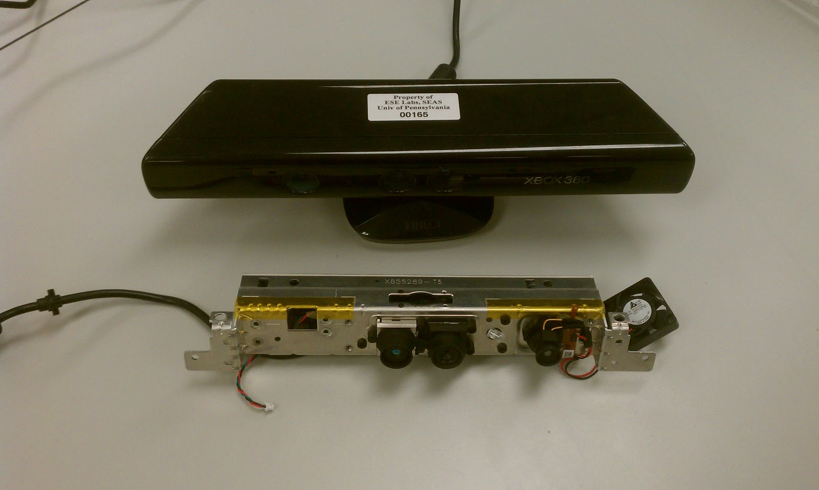
So motivated by these issues, we decided to switch to a slim 2000mAh, 3 cell LiPo battery that fits within the profile of the stripped down Kinect.
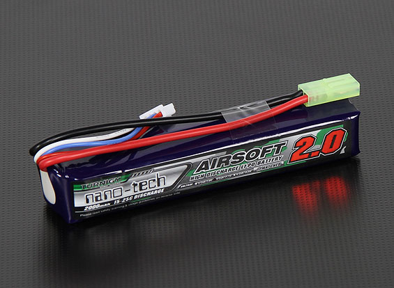
A 2000mAh, 3 cell LiPo battery delivers 11.V (3 * 3.7V) and can run at 2A continuously for an hour. Since our system averages less than 2A, it will last for over an hour on a single charge. Also, from our previous tests, we have verified that the Kinect — which is rated to work at 12V — will function as low as 8.5V. Not everything is perfect, however. We still need a voltage regulator to get 5V for the BeagleBoard and LiPo batteries require much more care to ensure they do not get overcharged or over-depleted.
For our new voltage regulator, we are using a more robust component that can take from 6-23V and output 5V at a maximum of 3A. This will allow us to eliminate the heatsink and use power directly from the LiPo instead of having a second power supply.
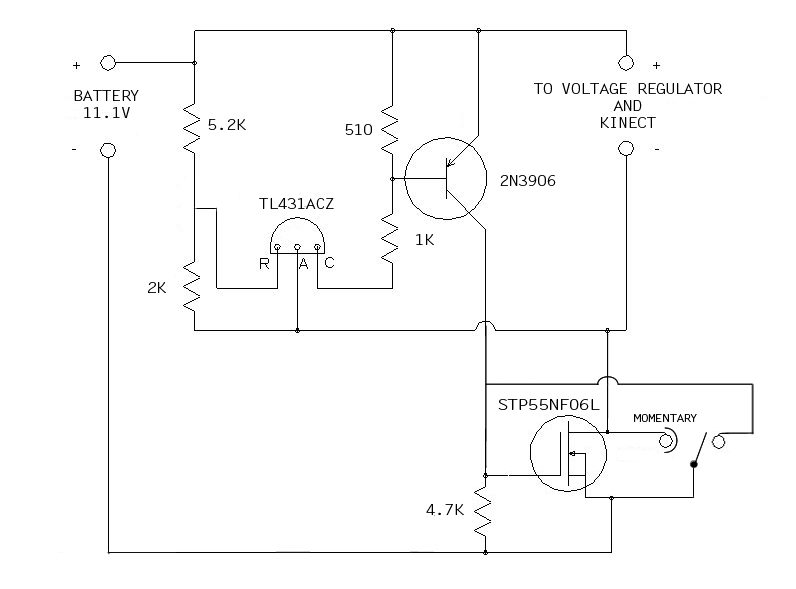
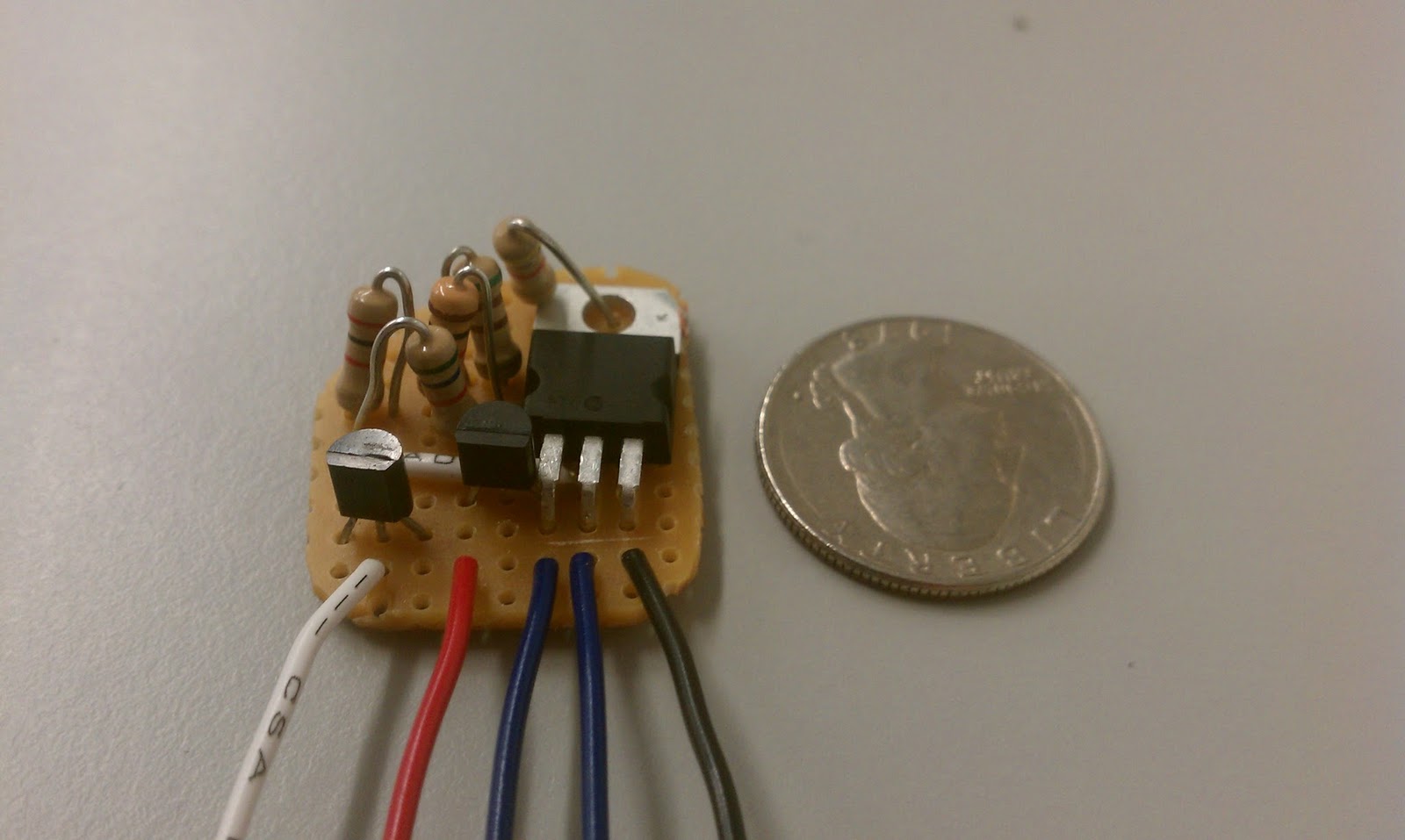
The final circuit we need for this system to work is a voltage cutoff circuit. Since LiPo cells lose their ability to accept a full charge if they are discharged beyond 3.0V, we need a circuit that cuts off power to the system when the 3 cell LiPo discharges to 9.0V (3 * 3.0V). Since this is the absolute limit, we built our circuit, with the help of Dan B., to cutoff at 9.5V. Dan’s circuit is operated by a single momentary switch that turns the device on, but no switch to turn it off. With our modifications, we will be able to operate the belt with a single (ON)-OFF switch — ‘ON’ in parenthesis indicates that the switch is momentary ON, static OFF. The circuit is shown below in schematic and PCB form:
Below is a video demonstrating proper function of these components, using a power supply instead of a LiPo to show the voltage cutoff.
PARTS LIST:
Battery
  • 2000mah 3S LiPo battery 15-25C — LiPo battery
  • Thunder-AC6-Charger-Power — charging station
  • LiPo guard charging bag — safety charging bag
  • Deans Ultra Connector Set — charging leads connectors
Voltage Regulator
  • 5VDC Voltage Regulator (BEC), Switch-Mode Type — 5V voltage regulator
Voltage Cutoff
  • STP55NF06L — power transistor
  • TL431ACZ — shunt regulator
  • 2N3906 — bipolar junction transistor, pnp
  • TIGC5B-6S-BL-NBL — switch option 1
  • SRN91-15BB — switch option 2
 

Team viSparsh

We’re almost ready to share some project updates, but in the meantime we wanted to share the final result of a group that we have been working with to replicate the Kinecthesia belt in India. Called viSparsh (a loose combination of ‘vision’ and ‘touch’ in Hindi), their team worked with us as part of the Young India Fellowship with UPenn. They successfully followed our blog to replicate our results, and with the help of a PandaBoard (instead of our BeagleBoard xM), they got it to work!
See their video demonstration below:
Great work guys!
viSparsh project blog: http://www.visparsh.blogspot.com/

Kinecthesia 2.0, Here We Come

First post in a while with a real project update!

BeagleBoard
For Kinecthesia 2.0, we will be using the BeagleBoard. “But you already are using the BeagleBoard!“, you say. Yes, but before, we were using the BeagleBoard XM, and now we will be downupgrading to the plain BeagleBoard. The BeagleBoard has multiple advantages for our project, but most importantly is its size. The BeagleBoard is 3″ x 3″ while the XM is 3.25″ x 3.25″. While this might not seem like a lot, it is actually a 15% reduction in area which, for a portable device, is not too shabby. This reduction comes with a reduction in processor speed, however. The BeagleBoard runs at 600 MHz compared to the XM’s 1 GHz. This should still be enough for the purposes of our device, while consuming less power!

Smaller Kinect
We also want to trim down the size of the Kinect because as you can see in the picture below, the Kinect is gigantic — too big for our device. Fortunately, there are plenty of how-to guides on how to tear down a Kinect. We borrowed a naked Kinect from Professor Mangharam’s lab and sure enough, it works great.


Building our own casing for the Kinect’s sensors will allow us have greater control of the design of the device while dramatically reducing weight and size. One option we have considered is to mount the processor and battery pack on the metal frame of the naked Kinect so that there are not bulky components all around the belt. The entire system (besides the vibrations motors which will still be around the waist) will all be enclosed in one case.

Update:
Stripped down Kinect specs:
length (without wings): 7 3/16 in
length (with wings): 9 1/2 in
height: 1 1/4 in
depth (without cameras): 1 3/16 in
depth (with cameras): 1 7/8
depth (with cameras and heatsink): 2 1/16 in
weight: 148 g


Kinect specs:
length (front): 11 1/8 in
length (back): 8 7/16 in
height (without base): 1 1/2 in
height (with base): 2 7/8 in
depth: 2 5/16 in
weight: 433 g


Kinecthesia version 1.0 weight: 1349 g (981 g without 16 AA batteries)


Better Vibration Motors
Our current system uses six vibration motors, however, we only have three vibration zones. Each zone has two vibrations motors working in parallel in order to increase the vibration sensation. We would like to replace these six buzzers with three stronger buzzers in order to reduce the complexity of the hardware. We would also like to change how the buzzers are mounted. Currently, the buzzers are mounted firmly to the rigid belt. This counteracts the forces of vibration and reduces the overall sensation. For increased sensation, the buzzers have to be able to move. We are experimenting with different ways to mount the buzzers, but one idea we are considering is mounting the buzzer on a wire or string (which is mounted to the belt) so it can rotate left and right around the axis of wire.

There are more updates to come, so stay tuned! Topics to look forward to: PWM on BeagleBoard, better obstacle detection, and reducing system delay.


New Video Overview

Below is the latest overview of the Kinecthesia project. Enjoy!


Download the video here.

Kinecthesia at Zeitgeist Americas 2011

I’m proud to announce that our project was chosen for Google Zeitgeist Young Minds! On top of that, I got to speak with Chelsea Clinton about Kinecthesia on the second day of the two-day conference which lasted from September 26-27, 2011. Here is the video:


Stay tuned for more Kinecthesia updates in the coming months…

First tests with Kinect and PC

Before we started on the Kinect Belt, we wanted to mess around with the Kinect on our PCs. We found the instructions to install the driver from this website. While the set up was pretty easy, there were some kinks when it came to transferring files around to different folders like they instruct. Once Microsoft comes out with its official SDK, this should be a lot easier.


We were able to run all of the demos, but our favorite was the Ogre demo. The program maps points on your body to a stick figure around which is the body of a dual-sword-bearing ogre. Check out the video below:


As we wait for our parts to come in, we will continue testing and modifying code with the Kinect, and start to program the Kinect Belt.

Kinect Belt

Our medical-themed project idea is called the Kinect-operated Vibro-tactile Belt for Aiding the Visually Impaired. As the name suggests, our product will use a Kinect to aid one’s vision. Our product will be aimed towards blind users.


Our plan is to mount a Kinect on a belt or waistband along with 3-6 vibration motors and a BeagleBoard. The Kinect will detect objects in the blind user’s path and vibrate the motors to warn him or her of the obstacles. For example, if there is an obstacle on the left, the left most motors will vibrate.


The BeagleBoard will take input from the Kinect and output which motors to vibrate. We are still figuring out how to power it wirelessly, but this similar project should help us out.


Here is a diagram of our project which includes the headphones/voice guidance project expansion: